SITE:


Automatic Camshaft Straightening Machine — Overview
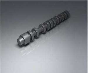
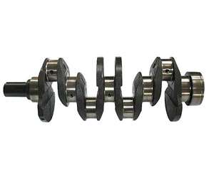
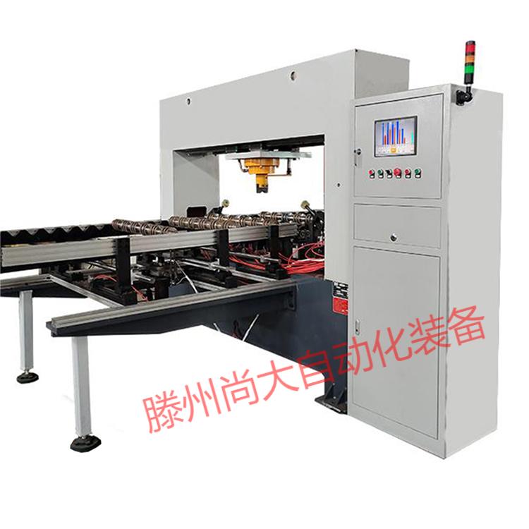
The automatic camshaft straightening machine is a purpose-built press configured around one of the most awkward parts in an engine plant: the camshaft. A camshaft carries a row of eccentric lobes, several bearing journals and often a drive flange. The machine supports the part on its journals, measures runout at the functional sections, and applies controlled correction bends until the shaft axis meets the straightness basis on the drawing.
In a camshaft line the machine sits after the distortion-producing operations, typically heat treatment, and ahead of finish grinding and assembly. Every part is measured before pressing and re-measured after, so the station is both a correcting press and an inspection gate driven by a stored part program.
Suitable workpieces
This model is configured for camshafts and similar multi-lobe eccentric shafts, with diameters from Ø5 mm to Ø600 mm and lengths from 100 mm toward the long-shaft range; longer parts are handled in sections. Supports, probe positions and press shoes are engineered from your drawings.
Cast, forged and assembled camshafts with multiple lobes and journals
Eccentric pump shafts whose functional surfaces must not be pressed on
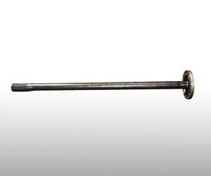
Shafts with end flanges or gears needing clearance during loading
Construction and key features
Runout measurement with lobe avoidance. The shaft rotates on its journals while probes read radial deviation, with 2-3 measuring points on shorter parts and more along long camshafts. Probe paths and supports never ride over a lobe.
Journal-specific supports and shoes. V-supports locate on round journals and the ram loads only a journal or plain inter-lobe section, keeping every stroke away from the hardened lobe profiles.
Force-and-displacement closed loop. An instrumented ram reports force and travel through the stroke; a per-part force ceiling, travel bound and abnormal-curve detection stop the cycle without a forced retry.
Recipe control and fast changeover. Each part number stores its measuring layout, support spacing, press points and force limits, so switching qualified camshafts is a recipe selection.
Optional automatic loading. Manual stations suit small batches; for high-volume lines, conveyors or robotic transfer can be added as a linked cell.
Selection and application notes
Swing diameter over the lobes, journal positions and overall length set the frame and support layout; press force follows the heat-treatment condition and section. Choose loading from your batch pattern, manual for mixed production, conveyors or robotics for long runs. Send drawings and process details and we will size it with you.
Frequently asked questions
Will the press contact or bruise the cam lobes?
The part is supported and pressed only on bearing journals or plain inter-lobe sections, probe paths skip the lobes, and the program geometry blocks any stroke that could cross a lobe profile. The hardened cam faces are protected throughout the cycle.
Can it straighten a bend between widely spaced journals?
Yes. Support spacing and press locations are configured to the journal layout on your drawing, so a bend between distant journals is corrected with supports set around that span. Long camshafts use additional measuring points and can be handled in sections.
Does it work for assembled camshafts with pressed-on lobes?
Assembled camshafts are assessed individually, because the lobe-to-tube joints must not be disturbed. The force ceiling and support layout protect those joints, and sample parts are run during acceptance to confirm the approach.
How do we change over between camshaft part numbers?
Each qualified number has a stored recipe covering measuring layout, support positions, press points and force limits. Changeover is a recipe selection with minimal change parts; the fixture family is defined at order time.
How is the result verified before acceptance?
Target straightness and its measurement basis are agreed in writing against your drawings, and your own camshafts are run in the factory before shipment. Before/after readings, stroke counts and peak-force logs are delivered with the parts, and repeated on site.
Engineering notes are in our camshaft and crankshaft straightening after heat treatment article; then send us your part drawings for a configured quotation. SHANGDA has built CE-certified automatic straightening machines since 2008.